The EGON Relay-Hub is a 12 – 24 Volt combined switching and fusing hub which can be used as a standalone or in combination with an EGON DC Hub, it can be an add on for switching and or extra circuits. It has been designed to make it extremely easy to integrate switching into your electrical DC system. It also works great as a combination of switched outputs and constant outputs with a battery box or small system installation where a more simplified version of the DC Hub is required.
It features:
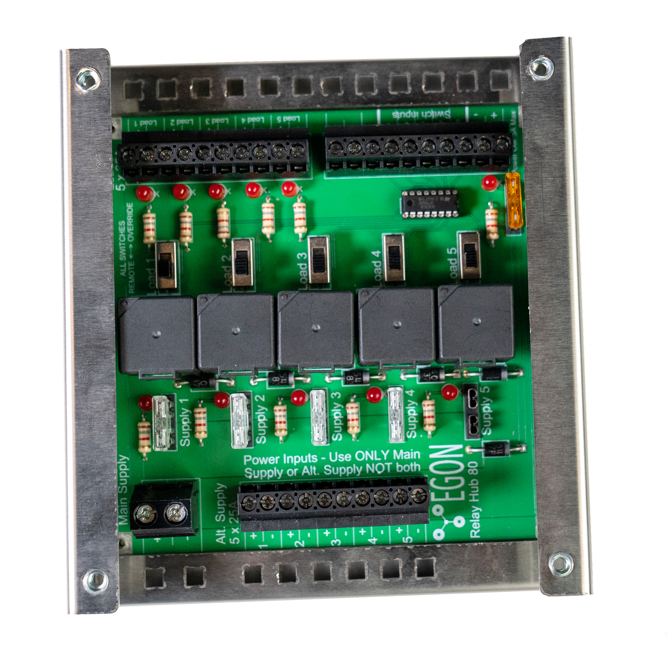
- Blown fuse indicators
- Outputs active indicators
- 5 individual switching / constant power supply circuits
- Override switches on the board for added redundancy
- Switch power supply circuit
- High quality screw connectors for easy connection of cables (no special tools needed)
- Sockets for 5 x standard automotive relays (available worldwide)
- 80A maximum current throughout
- 5 x 25A output circuits
The following connection diagram shows a combination of switched, constant power loads and external switching.
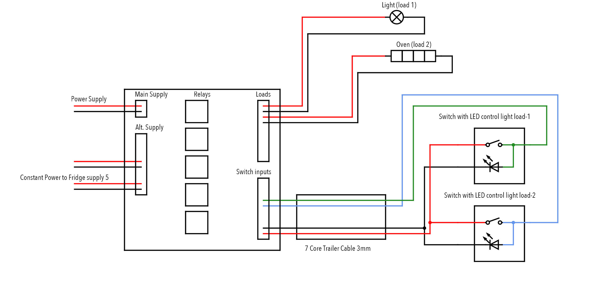
In our example drawing, Circuit 1 is being used to switch Load 1 through an external switch. Circuit 2 is being used to switch Load 2 through an external switch. Circuit 3 is being used to supply constant power to a fridge. Circuit 4 is not being used. Circuit 5 is being used to supply constant power to comms.
The trick to understanding the inner workings of the EGON Relay Hub is to understand that the circuits that are labeled Supply 1, Load 1, Alt. Supply 1, Switch Input 1 (all labeled on the circuit board) are all relating to the same circuit on the board.
How to connect
Supply Power
Connect the Main Supply with an external fuse (80A max.) to a power supply. This can be a DC-Hub, Battery Box, House- or Auxiliary-Battery or even your Start-Battery if you want to use this to power the electrical system that you are about to install. Now you have established the power supply to the board. Next step is to add a fuse to Supply 1 which will then power up the Alt. Supply 1 circuit and gives power to the Load 1 relay. The Load 1 relay when switched on will give power to the Load 1 pos and neg terminals.
To switch the relay, you can either use the override switch on the board which powers the activation circuit of the relay, or you can use an external switch.
Note: When the relay output is active the LED next to the Load 1 terminals will light up.
External Switch
To add an external switch, you can run a 3-core cable from the Switch input terminals on the board to your switch, For multiple switched circuits run 4, 5, 6 or 7 core cable. Add a fuse to the Power Out circuit (maximum 3amps).
This will power the Switch Inputs pos and neg terminals. These will act as a power supply for your switches. The Switch Inputs 1 through 5 will act as a signal return from the switch to activate the relay. Switch Input 1 will activate the Load 1 relay, Switch Input 2 will activate the Load 2 relay and so on.
Switched Load
To connect a switched Load (light, pump, oven, etc) use twin core cable and run it from your load to the Loads terminals on the board.
Constant Power Load
To connect a constant power load (fridge, comms, etc) use twin core cable and run it from the load to the Alt. Supply terminals on the board.
Note: You can use a circuit for switching and constant power supply at the same time. You just need to make that the fuse rating is chosen accordingly to being able to supply the switched load and the constant load. Please make sure that the fuse rating stays within the safe working limits of the connected cables and components that are connected to the EGON Relay Hub.
Recommended torque settings for 25A connectors: 0.6 Nm