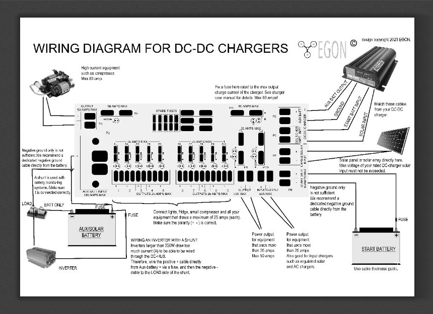
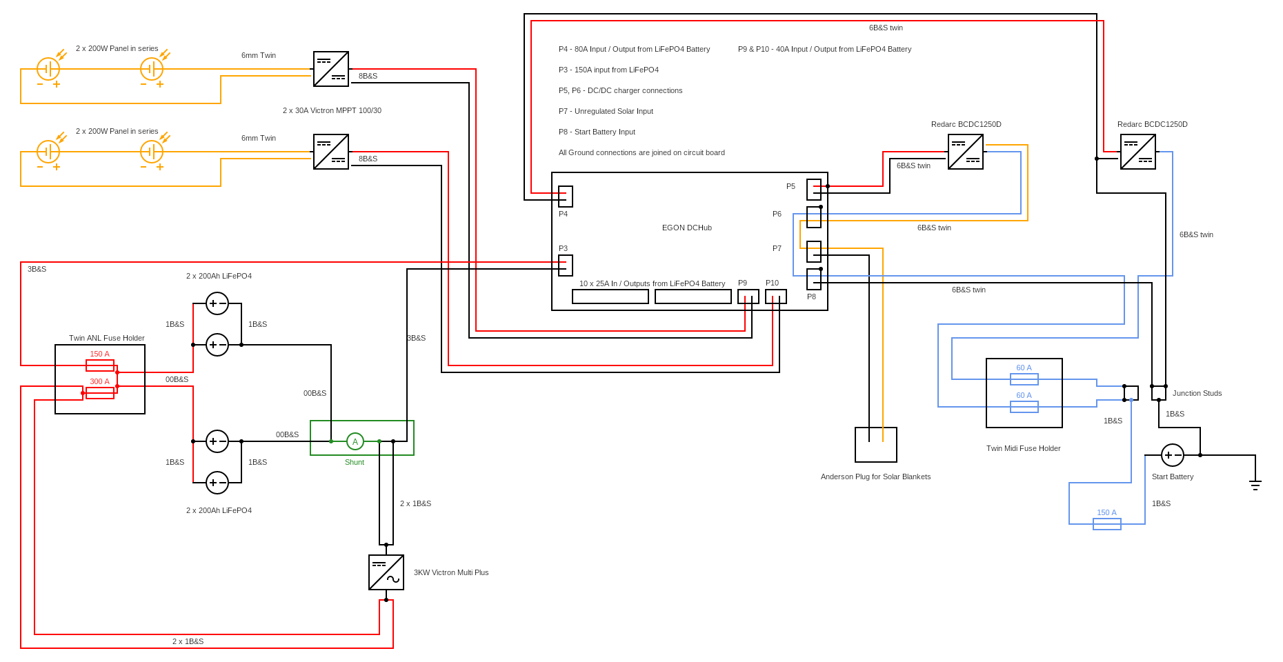
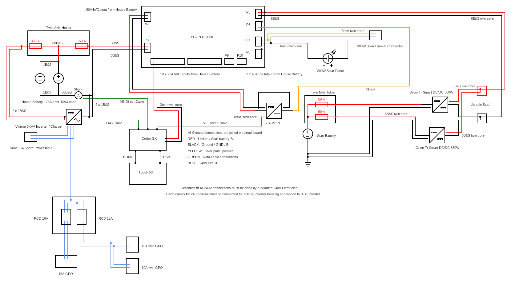
Watch our videos on How to connect the EGON DC-Hub integrated fuse box
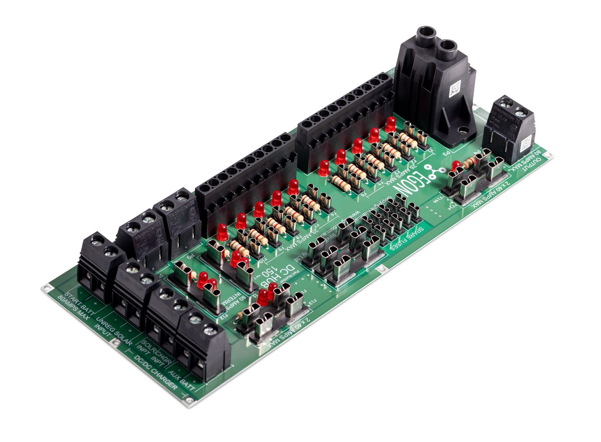
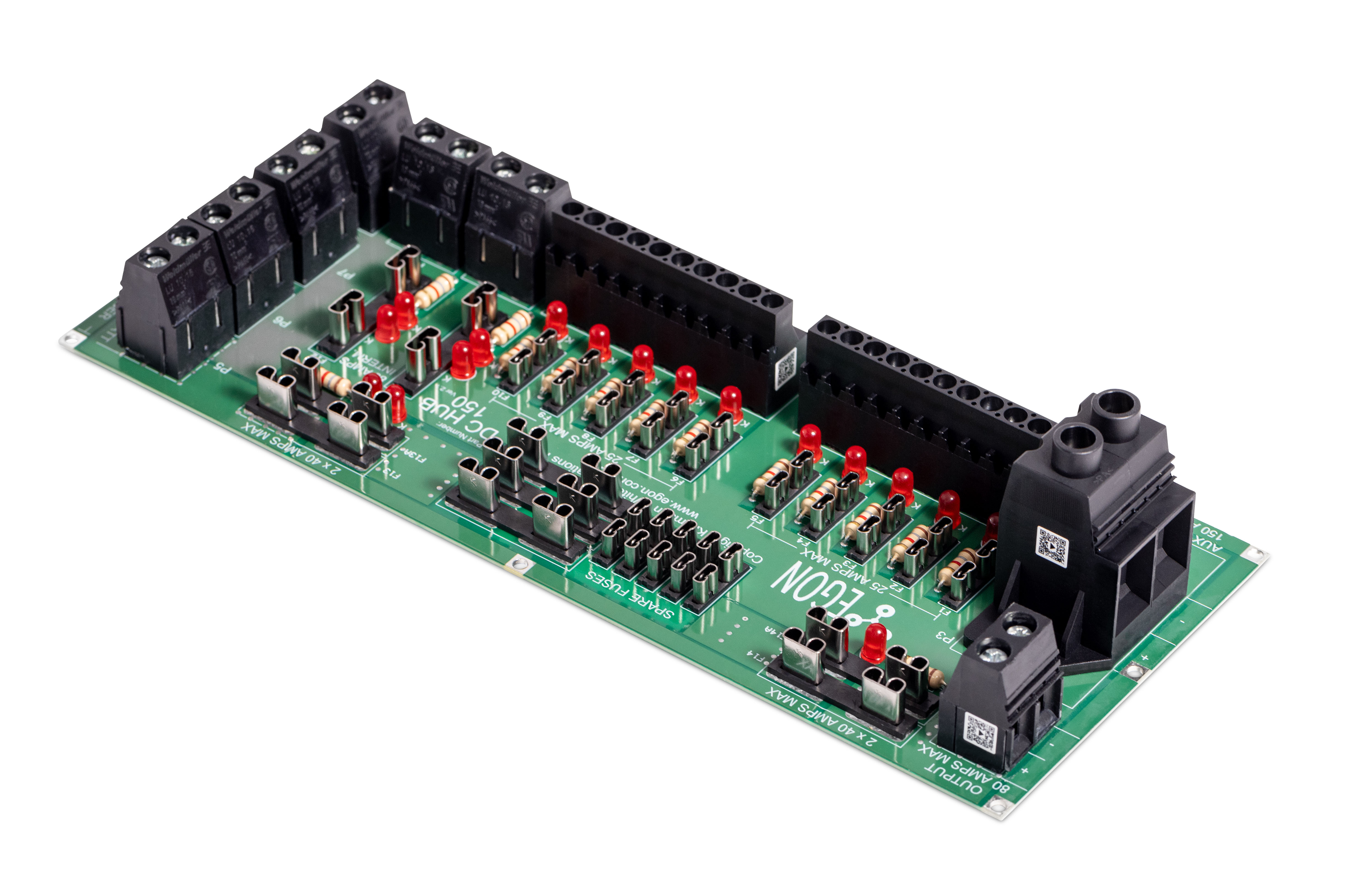
Launched in September 2022, the EGON DC-Hub version 2.0 and 2.1 (now shipping) are suitable for 12 and 24V systems with high-output connectors upgraded from 50A to 80A each. Version 2.1 (now shipping) has the addition of the permissible input current increased to two 40A connectors that reduce voltage-drop during long-duration, high-current charging from DC-DC chargers.
Version 2.1 wiring diagrams. Click to enlarge
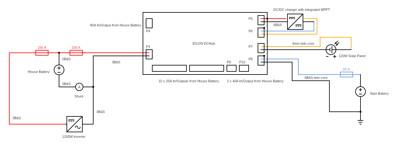
Connection Example: Standard DC system
For a standard DC system with mid-sized inverter, single House battery and DC/DC charger with integrated
MPPT controller you can use the following connection example.
Red cables are connected to house battery. Blue cables to Start battery. Yellow cables to unregulated solar.
CONNECTOR EXPLANATION
The house (aux) battery (AGM, LiFePO4, flooded Lead Acid, etc…) connects to connector P3 and needs an external 150A fuse at the house battery bank. Any size battery bank can be used. The DC-Hub is not limited to a certain Amp Hour size.
The start battery gets connected to connector P8 and needs an external fuse at the start battery of your vehicle.
Solar panels can be connected to connector P7.
Both connectors P8 & P7 positive cables are linked to connector P6 to simplify the connection to a DC/DC charger with integrated MPPT controller.
All ground connections of every single connector are linked on the circuit board.
A DC/DC charger with integrated MPPT controller (Redarc BCDC range, Enerdrive DC/DC, etc…) can be connected to connector P5 with charge output and ground and to connector P6 for solar and start battery input.
All loads (like compressors, fridges, lights, charge ports, etc…) can now be connected to the remaining connectors and will be automatically connected to the house battery.
ATTENTION:
Connectors P4 & P5 can handle a constant 80A load. To prevent the Maxi Fuses from overheating please use 2 Maxi Fuses.
Example: When connecting a DC/DC charger to connector P5 that requires a 60A fuse insert 2 x 30A fuses into fuse holder F13 & F13A.
Do the same with connections to connector P4 and use the fuse holder F14 & F14A.
Connectors P9 & P10 can only handle 40A constant load or 80A intermittent load. Currents of 40A must not be exceeded for more than 10 minutes at a duty cycle of 50% (10 minutes on / 10 minutes off) to allow the contacts to cool.
